| . Here is the flywheel mounted on the V12 PTO. I had to
make an adapter to get the gearbox axle bushing in place. |
1
|
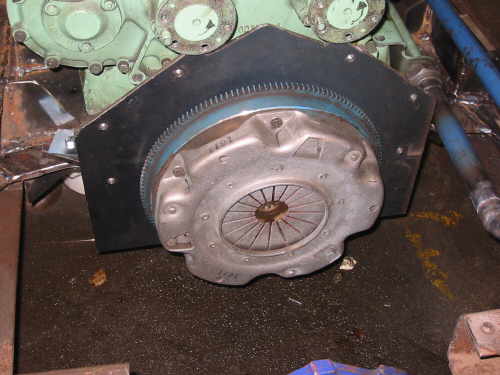 |
Clutch and flywheel mounted on the engine. |
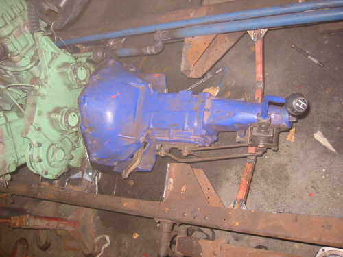
| And finally the gearbox in place, i did not make a heavy
rear gearbox mount since the engine is mounted solid into the frame, so
the gearbox don't have to carry any weight. |
 |
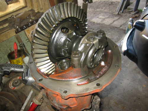 |
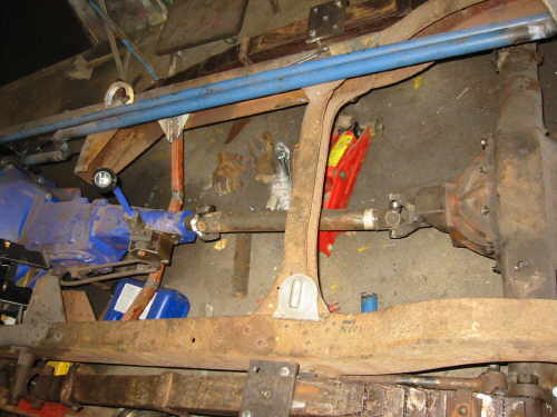
Then i took a look into my old Ford 9" axle i had laying around, it's
a 2,78 to 1 .
And it will propel my "car" at lightning speed (not ;-) |
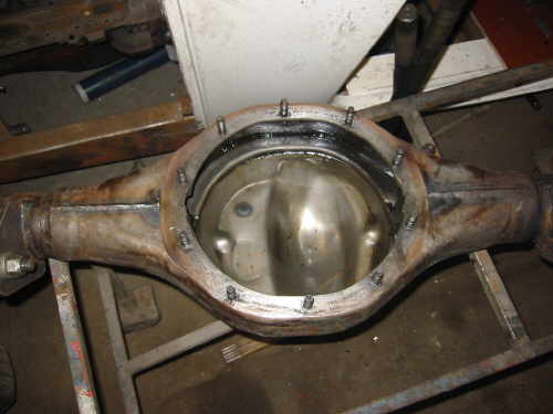
| I cleaned out the inside of the axle to. Since i used the "gas axe"
to cut of the original mounts. |
 |
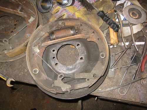 |
The brakes got a refurbish to. Bought some new brake cylinders
(not mounted in this picture).
The other parts where reusable.
|
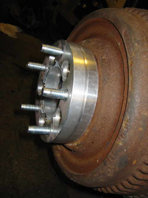
| I got a set of 18" Wire wheels with usable tires ;-) The
drawback was that the they had a 5 inch bolt pattern. But luckily i found
a low rider web page that had adapters between 4,5 inch five bolt
to 5 inch 5 bolt. |
 |
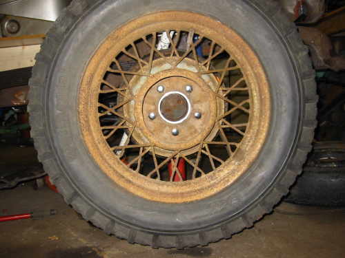 |
Here is the wheel mounted for the first time,I will sandblast the wheel
and paint them later on. |
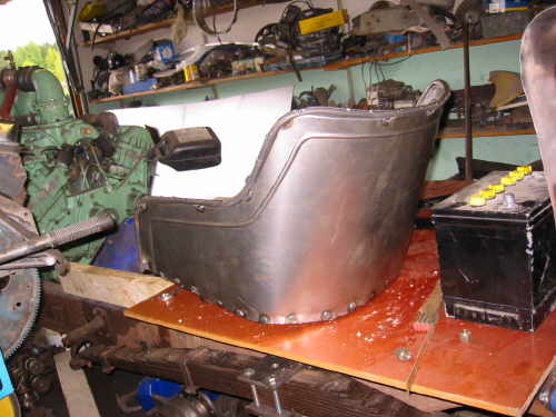
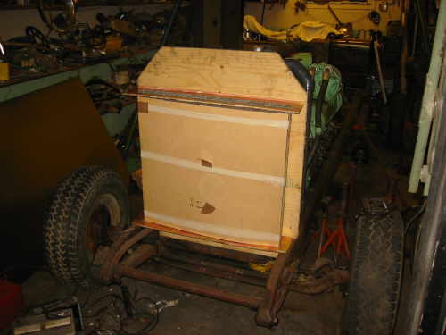
Then it was time to cover the butt (make a seat)..
|
 |
 |
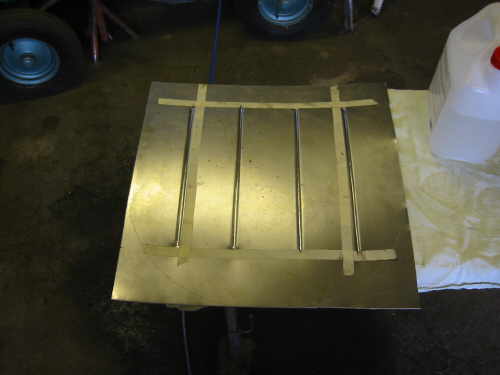
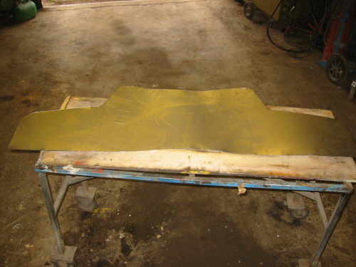
Got the shape from one of my kitchen chairs. |
Used a sheet to design the backrest, then i cut it out of some 1 mm
sheet steel. Its cheaper to make mistakes in paper.
|
 |
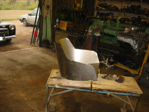 |
Testing the design.. |
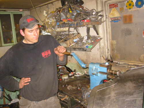
| Henrik helped me turning the crank.. |
 |
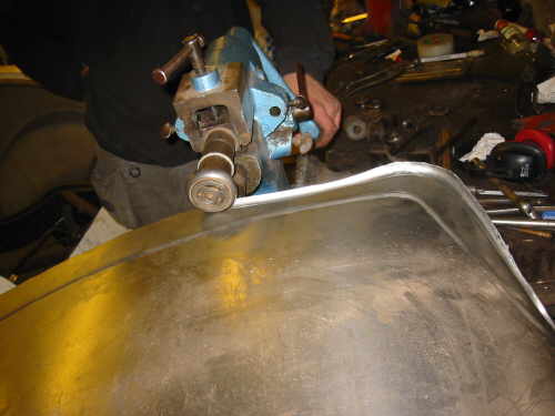 |
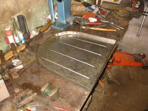
We made a thin line 40 mm into the sheet. then we used some bigger rollers
and made an edge. That i filled with an 8mm rod later.. |
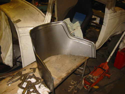
Backrest ready.
. |
 |
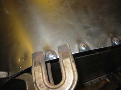 |
Punched some holes at the bottom of the backrest, and then plug welded
the bottom part to the bottom part
..
|
| Here you can see the 8mm rod spot welded at the seat edge. |
 |
 |
After the seats, it was time to start with the steering. I had to shorten
the steering column. and add a ford column piece so my BIG steering wheel
would fit. |
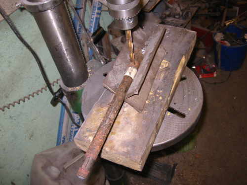
| This is a good way to drill holes into tubes, its two pieces of angle
iron welded together. |
 |
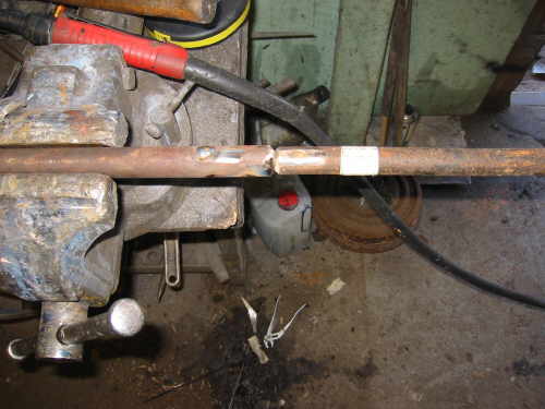 |
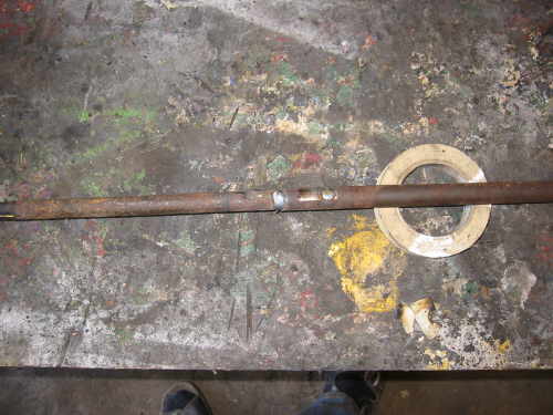
I chamfered the ends to get a good weld penetration. and also plug
welded the holes i drilled into the steering shaft. |
Ready. Don't grind welds on steering parts, and be sure that you have
real good weld's your life can depend on them.
|
 |
 |
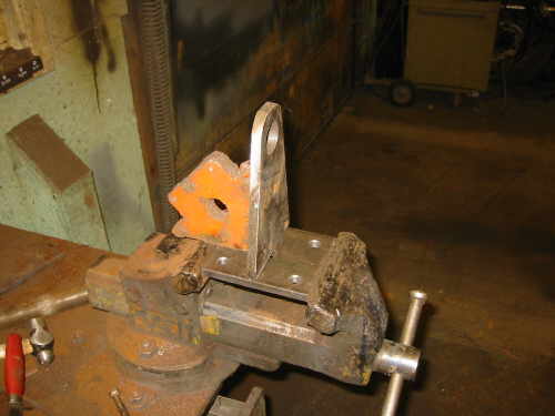
Mikael is helping me find out the location of the steering box. |
| Used some 6mm steel plate, and the first weld is there. |
 |
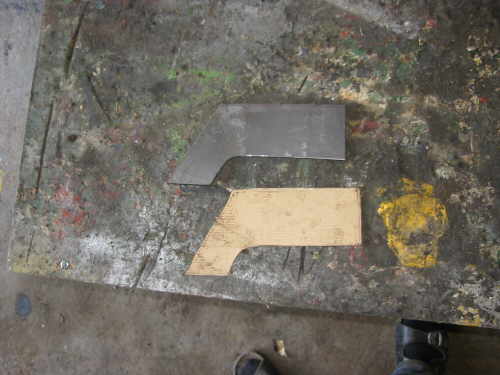 |
I had to make some side pieces, paper is cheaper then steel, so use
it as pattern. |
| Starting to look the business now. the steering box is a Volvo of course
:-) |
 |
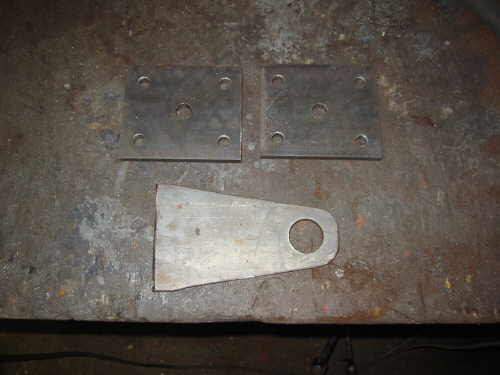 |
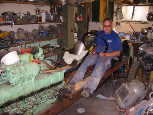
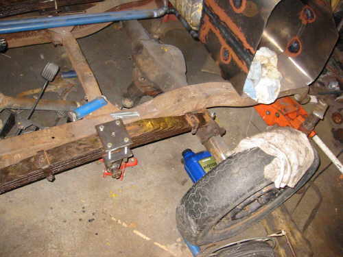
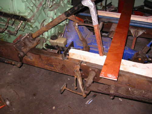
After the steering was sorted . I started to mess with the rear
axle spring mounts, i did not have the original Buick parts so i had to
make them myself. |
| This is the lower part of the spring mount. |
 |
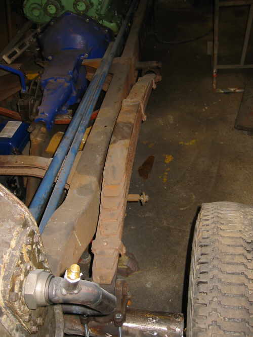 |
This is the old rusty spring . This mounting style is called cantilever.
|
I had to take the springs apart, and grind of years of old rust, and
then greased them up. It took me two evenings to do this.
|
 |
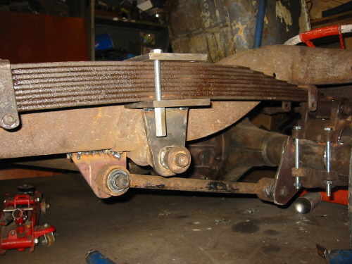 |
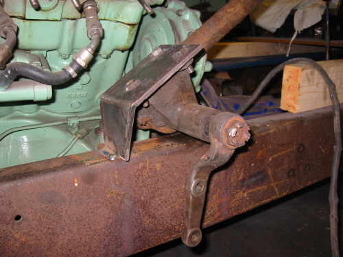
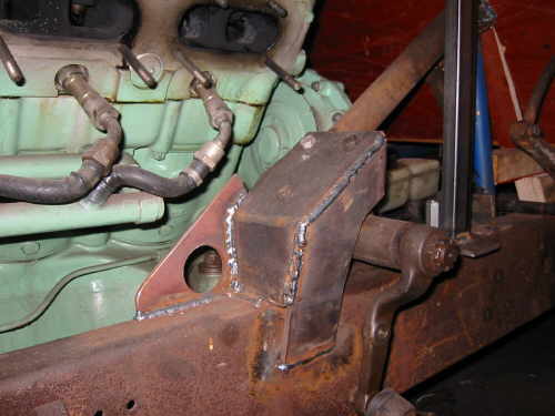
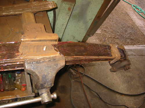
First i had to try out the suspension geometry, Since the Buick had
a solid props haft like an old Ford taking car of the axle position. Since
i did not have that i had to add a lower bar (Volvo) to get a four link
type of suspension. later i added plate on both sides of the bar and more
bolts to hold the spring. |
| Something like this. |
 |
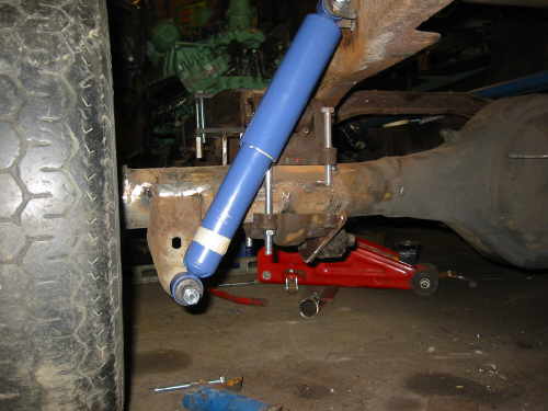 |
Reused the axle shock mounts, shocks are Volvo of course the cheapest
i could find :-) |
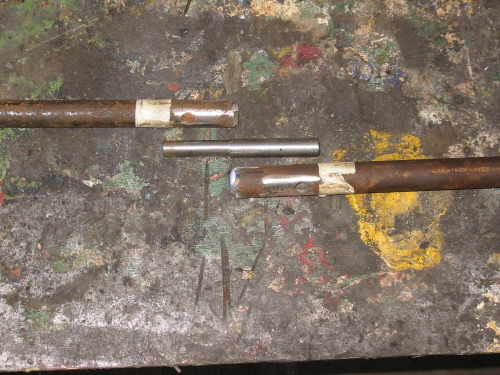
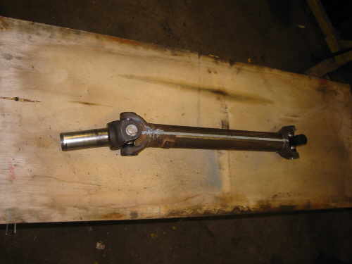
| This is the props haft consist of Volvo props haft + Chevy yoke parts.
And i know it wont hold up to 600 hp, but remember mm building the "car"
just to being able to move under own power so people can enjoy the awesome
sound. |
 |
 |
Prop shaft mounted. |
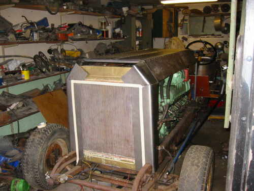
| Then it was time to look at the other end of the vehicle,first i made
a plywood pattern to define the maximum size of the radiator. Then a friend
of mine got me a core that could handle 600 hpr. |
 |
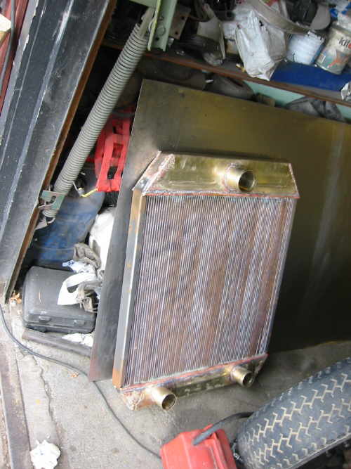 |
The same friend made some brass tanks to fit the core. |
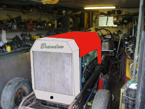
| This is a Photo shop exercise, to get a picture of how it will look.
The color match the vacuum cleaner at least. |
 |
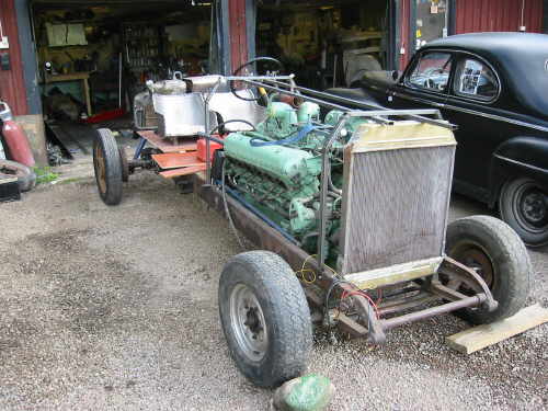 |
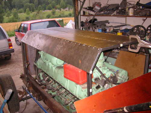
I made a couple of U shaped bows to carry the hood. |
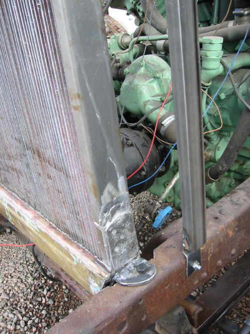
| To fit the radiator i made flat iron cradle, and some L shaped pieces
and soldered them to the brass tanks. |
 |
 |
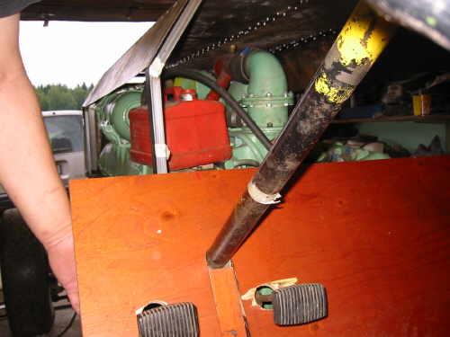
When the radiator was taken care of, i needed to have some brake and
clutch pedals. |
| Guess what i used for parts (Volvo of course). Maybe I'm building the
new X90 :-) |
 |
 |
Hood mockup Once again paper is cheaper than steel. |
| Some sheets of steel and piano hinges, and hundreds of pop rivets. |
 |
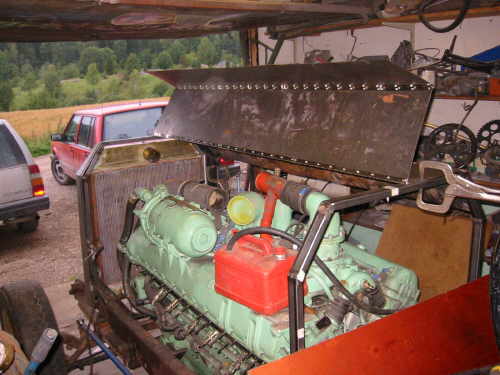 |
Starting to look functional. |
I have also started to make a cover for the radiator, you have to wait
for the next update to see the result
|
 |
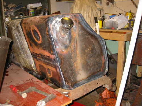 |
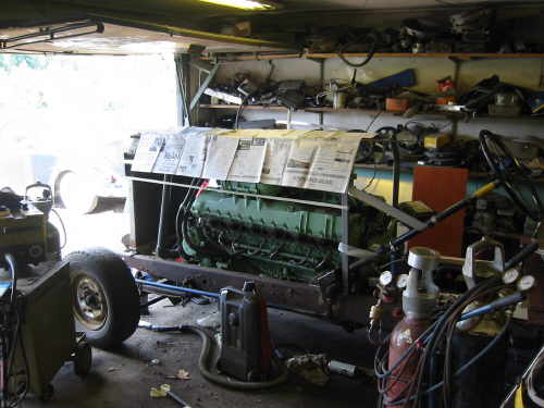
After a year I've also welded the last part of the gas tank, you
get no point if you guess where the cap came from (Volvo ;-)) |
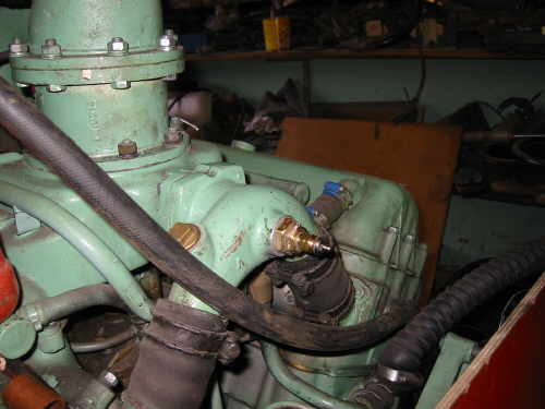
| Finally for this time, i mounted the sending unit for water temp, and
guess what its not a Volvo part!!! |
 |
| Here is a picture captured from a MPG file taken on my first test
start. Now i really need to get my flywheel back.
By the way if you want to see the "movie" here is the link.
3.9 MB so it takes a while with a Modem.
Its Alive |
|